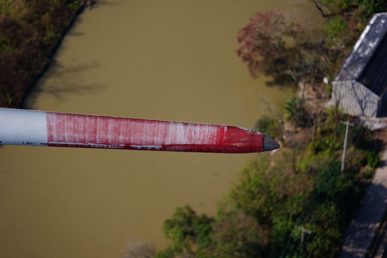
Autonomous wind turbine blade inspection uses a controlled flight path to capture repeatable, position-linked images of defined blade surfaces. The workflow combines flight planning, image-quality and coverage checks, AI-assisted defect detection, human review, and structured reporting for maintenance decisions.
The word autonomous can be misleading. It does not mean that a drone makes an engineering decision by itself or that a pilot is no longer responsible for safe operation. It means that the repeatable parts of the inspection—flight geometry, stand-off distance, camera angle, capture sequence, and surface coverage—are controlled by a purpose-built system rather than improvised during every flight.
That distinction matters because the output of a blade inspection is not a collection of attractive aerial images. It is evidence that must be complete enough to review, consistent enough to compare, and structured enough to support maintenance action.

What is autonomous blade inspection?
Autonomous blade inspection is a form of external visual inspection in which a drone follows a planned and controlled route around a stopped wind turbine rotor. The system captures high-resolution imagery of designated blade surfaces and links each image to the turbine, blade, side, and location it represents.
A complete platform typically includes five layers:
- Flight and safety control for positioning the aircraft around the rotor.
- A capture protocol defining the surfaces, angles, overlap, and image quality required.
- Field quality assurance to confirm that the evidence is usable before leaving the site.
- Analysis and human review to find, classify, locate, and validate possible defects.
- Reporting and asset records that turn findings into inspection history and maintenance inputs.
An off-the-shelf drone can take useful blade photographs, but it does not automatically create an autonomous inspection workflow. The operational value comes from controlling the full evidence chain.
The autonomous inspection workflow
1. Prepare the turbine and inspection plan
The team identifies the turbine, rotor configuration, blade dimensions, site constraints, required surfaces, and reporting standard. The turbine is normally stopped and positioned according to the inspection method. Weather, airspace, communications, offshore logistics, and site safety controls are checked before launch.
The inspection plan should state what constitutes completion. For an external visual campaign, that may include the leading edge, pressure side, suction side, and trailing edge of all three blades, plus any requested tower, nacelle, or foundation evidence.
2. Establish the flight geometry
The system calculates or adapts the flight path around the blade. A controlled stand-off distance and near-normal camera angle help preserve effective image resolution and make apparent defect size easier to estimate.
Repeatability is more than returning to the same GPS coordinate. The blade can move, flex, rotate, and appear differently under changing light. A purpose-built workflow uses information from the aircraft and inspection system to maintain the intended relationship between camera and blade surface.
3. Capture each required surface
The aircraft moves through the defined passes while the camera collects overlapping images. Clobotics IBIS is designed to capture the leading edge, pressure side, suction side, and trailing edge through four passes per blade.
Useful inspection imagery depends on several variables:
- sufficient spatial resolution at the blade surface;
- controlled focus, shutter speed, and motion blur;
- an angle that does not distort or hide the surface;
- enough overlap to avoid coverage gaps;
- exposure that retains detail on light composite surfaces;
- traceable blade-side and position metadata.
More images are not necessarily better. The aim is complete and reviewable coverage without creating unnecessary data volume.
4. Check image quality and coverage in the field
The inspection should be checked before the turbine is released and the team demobilizes. A coverage view or blade stitch can reveal missing sections, blur, glare, incorrect distance, or images assigned to the wrong surface.
This field QA step is economically important. A gap discovered during analysis may otherwise require another turbine stop, pilot visit, vessel movement, or offshore mobilization.
5. Upload and organize the evidence
Images and flight metadata are associated with the correct wind farm, turbine, blade, surface, and inspection campaign. This asset structure allows a reviewer to navigate the blade logically rather than search through an unstructured photo folder.
The structure also creates an audit trail: teams can see what was inspected, when it was captured, which evidence supports a finding, and how the finding changed in later campaigns.
6. Use AI to suggest possible defects
Computer vision can scan inspection imagery for visible conditions such as leading-edge erosion, coating damage, cracks, lightning-related marks, trailing-edge damage, contamination, or missing add-ons. It can also segment blade surfaces and help organize clear imagery separately from areas needing review.
Research from DTU has demonstrated deep-learning systems that suggest damage locations and types from drone inspection imagery. The research also reinforces a critical design principle: automation is most useful as a way to focus expert attention, not as permission to skip validation. DTU research on deep-learning-aided drone inspection
7. Apply human quality assurance
A qualified reviewer validates suggested findings, checks uncertain images, corrects classification errors, and interprets the evidence in its engineering context. Human QA is especially important when:
- the indication is small, partially hidden, or affected by glare;
- severity depends on depth or subsurface extent that RGB imagery cannot prove;
- a finding is near a structurally sensitive area;
- the consequence could include shutdown or urgent repair;
- historical images show an ambiguous change;
- the inspection method did not achieve full confidence.
Automation can reduce repetitive screening and improve consistency. It does not convert a visual indication into a structural diagnosis without the appropriate evidence.
8. Produce a decision-ready report
A useful blade inspection report should include:
- wind farm, turbine, blade, date, method, and inspection scope;
- coverage and image-quality status, including limitations;
- defect type, blade side, spanwise and chordwise location;
- annotated source imagery and an indication of scale;
- severity or priority with the applied classification logic;
- reviewer confidence and any need for targeted follow-up;
- recommended action: monitor, inspect further, repair, or escalate;
- links to earlier findings and completed repairs where available.
The report should distinguish observation from interpretation. “Visible linear indication at 72% span” is evidence. “Structural crack requiring shutdown” is a conclusion that may need closer inspection or engineering assessment.
Flight repeatability: why it matters
Repeatable capture makes three kinds of decisions more dependable.
First, it improves coverage confidence. When each blade follows a defined protocol, missing areas are easier to detect.
Second, it improves comparison over time. Similar angle, distance, and location make it easier to determine whether erosion or another visible condition is progressing.
Third, it improves analysis consistency. Computer vision performs better when image scale and geometry vary within controlled limits.
This is why Clobotics treats IBIS capture and IRIS analysis as one evidence workflow. The aircraft collects structured external blade imagery; IRIS organizes findings, supports review, and retains the inspection record.
Drone blade inspection vs. rope access
Neither method is universally superior. They answer different questions and can be combined in a risk-based program.
| Dimension | Autonomous drone inspection | Rope-access inspection |
|---|---|---|
| Safety exposure | Keeps inspection personnel away from the blade surface; still requires aviation and site controls | Places trained technicians at height and requires a mature access and rescue system |
| Speed | Rapid external visual coverage; Clobotics IBIS can complete a full turbine in as little as 15 minutes under suitable conditions | Slower for full-surface coverage, but efficient when a known location needs close examination or repair |
| Data consistency | Controlled routes, distance, angle, and capture sequence improve campaign repeatability | Quality depends more heavily on technician access, documentation discipline, and time available |
| Image coverage | Strong for systematic external surface coverage when the capture protocol is completed | Excellent local visibility, but full-blade documentation can be time intensive |
| Defect detection | Effective for visible external indications; cannot by itself prove hidden depth or internal extent | Supports close visual assessment, touch, cleaning, tapping, and selected non-destructive tests |
| Weather dependency | Constrained by wind, precipitation, visibility, aircraft limits, and regulation | Also weather constrained; access may have different wind and surface-condition limits |
| Cost structure | Favors repeatable fleet-scale screening and frequent campaigns | Favors targeted close inspection, combined inspection-and-repair scopes, or sites where flight is impractical |
| Repair readiness | Produces location and imagery that can support scoping and quotations | Technician can confirm local condition and may perform work during the same access campaign |
| Offshore suitability | Can reduce time near the blade, but still depends on vessel, turbine stop, flight permissions, and offshore weather | Valuable for hands-on work, but offshore access, rescue planning, and weather windows add complexity |
| Audit trail | Structured imagery and metadata can create a consistent digital record | Can be strong when photographs, locations, tests, and notes are documented to the same standard |
The practical pattern is often broad screening followed by targeted escalation. Autonomous inspection establishes repeatable external coverage. Rope access or another targeted method is then used where the evidence requires touch, cleaning, testing, or repair.
How autonomous inspection can reduce offshore inspection costs
Autonomous inspection reduces offshore cost when it removes avoidable vessel time, repeat mobilization, work-at-height exposure, and unnecessary close-access scope—not merely because a drone flies faster. The business case must be evaluated at campaign level, including logistics, turbine availability, data quality, reporting, and the cost of obtaining missing evidence later.
The main cost levers are:
- Shorter external capture: repeatable flight paths can reduce the time needed to document full external blade surfaces under suitable conditions.
- Field coverage verification: finding a missing or unusable blade section before leaving the turbine helps avoid a second vessel movement or campaign visit.
- Targeted escalation: structured external evidence helps teams reserve rope access, NDT, or internal inspection for findings that genuinely require closer proof.
- Campaign consistency: standardized capture and reporting reduce manual rework when multiple turbines, crews, or sites must be compared.
- Better repair scoping: location-linked evidence can support engineering review, quotation, materials planning, and work packaging before a repair team mobilizes.
- Combined planning: where operationally and technically appropriate, inspection scopes can be coordinated with other offshore activity to reduce separate mobilizations.
These benefits are not automatic. Offshore economics still depend on vessel day rates and availability, transfer and launch arrangements, weather windows, aviation permissions, turbine stop requirements, distance from port, number of turbines, and whether the inspection result is accepted for the intended engineering or contractual decision.
A credible vendor comparison should therefore ask for a campaign model rather than one headline price. Compare total offshore personnel and vessel time, turbines completed per workable day, coverage acceptance rate, repeat-visit rate, report turnaround, escalation requirements, and whether the resulting evidence can be reused for repair planning and future trend comparison.
Where robotic blade inspection fits
The term wind turbine inspection robot can refer to several systems. Aerial drones collect non-contact external imagery. Internal crawlers travel through accessible blade interiors. Surface-crawling robots may carry ultrasonic or other sensors for targeted subsurface inspection.
Clobotics uses different systems for different evidence needs:
- IBIS autonomous external blade inspection for repeatable surface imagery.
- KIWI internal blade inspection for accessible internal structures.
- HUMMINGBIRD lightning protection testing for electrical continuity evidence.
- IRIS Wind Intelligence for analysis, reporting, and maintenance planning.
Weather, offshore, and safety limits
Autonomy does not remove operating limits. A safe and useful inspection depends on:
- aircraft wind and precipitation limits;
- visibility, glare, and contrast on the blade surface;
- rotor stability and approved turbine positioning;
- local aviation rules and site permissions;
- electromagnetic, communications, and GNSS conditions;
- obstacles, adjacent turbines, vessels, and personnel;
- launch and recovery space;
- offshore transfer, vessel motion, salt spray, and recovery planning;
- competent operators and an emergency procedure.
Weather affects data quality as well as flight safety. An inspection completed at the edge of the operating envelope may still fail if blur, spray, deep shadow, or unstable geometry makes the imagery unsuitable for review.
What autonomous inspection cannot prove
Standard RGB drone inspection primarily shows external surface condition. It may indicate a crack, impact, lightning mark, open edge, or coating failure, but it cannot reliably determine every defect’s depth, subsurface propagation, bond integrity, or internal structural consequence.
The correct response to uncertainty is not a more confident label. It is qualified engineering review and, where necessary, a suitable approved follow-up inspection.
How to evaluate a blade inspection platform
Ask a provider to demonstrate the entire chain:
- Which surfaces are included, and how is complete coverage verified?
- How are distance, angle, resolution, blur, and exposure controlled?
- What happens when the field QA check fails?
- How are images linked to blade location?
- Which conditions can the analysis suggest, and which are outside its scope?
- Who reviews AI findings and how are corrections recorded?
- Can reports distinguish evidence, severity, confidence, and recommendation?
- Can findings be compared across inspection years and vendors?
- Can the data be exported and integrated with maintenance systems?
- How does the workflow trigger closer inspection or repair?
The strongest blade inspection platform is not the one with the most autonomous flight. It is the one that produces repeatable evidence and preserves the path from observation to action.
The practical takeaway
Autonomous inspection is best understood as a controlled evidence system. Flight automation makes external blade capture faster and more repeatable; image QA protects coverage; AI assists screening; human reviewers validate the result; and a blade inspection platform turns the evidence into a usable maintenance record.
Drone inspection and rope access should not be treated as opposing ideologies. Use autonomous drones for scalable external screening and trend evidence. Use internal inspection, close access, or another approved follow-up method when the maintenance question requires additional proof.
Learn more about IBIS autonomous blade inspection, read the Brazil inspection scale-up case study, or explore Wind Intelligence for blade lifecycle management.