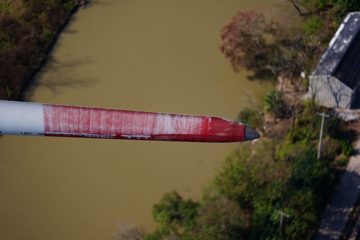
Wind turbine blade inspection combines external and internal visual evidence with close inspection and lightning protection testing where required. A decision-ready report links each finding to its blade location, type, size, progression, confidence, risk context, and recommended maintenance action.
The purpose of inspection is not to find the largest number of anomalies. It is to reduce uncertainty about blade condition and decide what to monitor, investigate, repair, or escalate.
That requires more than images. Teams need the right inspection method for the suspected damage mechanism, consistent defect classification, reliable location data, historical comparison, and a clear path into repair planning.
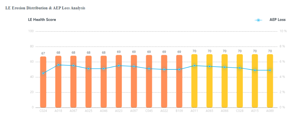
What does wind turbine blade inspection cover?
A blade inspection program may examine:
- external coatings and aerodynamic surfaces;
- leading and trailing edges;
- blade tips, receptors, add-ons, and drainage features;
- root, shell, spar cap, webs, and bondlines where accessible;
- signs of lightning attachment and the lightning protection path;
- earlier repairs and leading-edge protection systems;
- changes in known findings across time.
No single method sees all of these equally well. A strong program starts with the maintenance question and selects the evidence needed to answer it.
How often should wind turbine blades be inspected?
Wind turbine blade inspection frequency should be risk-based rather than set by one universal calendar rule. The appropriate cadence depends on the turbine and blade model, age, operating environment, earlier findings, repair history, contractual requirements, access constraints, and the consequence of allowing damage to progress.
A defensible inspection plan normally combines three types of trigger:
| Trigger | When it is useful | What the program should decide |
|---|---|---|
| Scheduled baseline | At commissioning or at an owner-defined recurring interval | Establish comparable condition evidence across the fleet |
| Risk-adjusted follow-up | When a known finding, earlier repair, ageing blade population, or exposed site requires closer observation | Shorten or extend the next interval using documented evidence |
| Event-driven inspection | After lightning, hail, severe weather, suspected impact, abnormal performance, or another relevant event | Determine whether targeted external, internal, LPS, or close inspection is required |
The calendar interval is only one part of the program. Operators should also define what evidence is required, which inspection method can produce it, what change will trigger escalation, and how the next inspection will reproduce the same blade location and image geometry. OEM instructions, applicable regulation, insurer and warranty requirements, and qualified engineering judgment remain controlling inputs.
At fleet scale, the aim is not to inspect every turbine at the same frequency. It is to maintain a documented baseline, identify higher-risk cohorts, monitor known findings consistently, and allocate inspection effort where delayed detection would have the greatest operational consequence.
Blade inspection methods
External visual inspection
External visual inspection looks for visible surface conditions across the blade. Evidence may be collected from the ground with a telephoto camera, from a drone, from a platform, or by a rope-access technician.
It is appropriate for conditions such as visible erosion, coating loss, cracks or linear indications, impact marks, open trailing edges, lightning marks, damaged add-ons, contamination, and previous repair condition. It is less conclusive when the concern is hidden below the surface.
Drone blade inspection
Drone inspection can capture systematic external imagery without placing a technician on the blade. Autonomous systems control flight geometry and capture sequence to improve coverage and comparison across turbines.
Its strengths are speed, repeatable surface evidence, fleet scalability, and a strong digital audit trail. Its limits include weather, flight regulation, image quality, and the inability of ordinary RGB imagery to establish every subsurface condition.
See How Autonomous Wind Turbine Blade Inspection Works for the full data-capture and review workflow.
Close visual and rope-access inspection
Close access allows a technician to clean a surface, examine texture, touch or probe an indication, perform tapping or selected non-destructive tests, and document a repair scope. It is particularly useful for resolving an uncertain finding or combining inspection with immediate work.
The tradeoff is that full-blade coverage takes more time and places personnel at height. Access, rescue planning, weather, and technician availability become major campaign constraints.
Internal blade inspection
Internal inspection examines accessible structures inside the blade, including root areas, webs, laminates, and bondlines. Manual entry may be practical near the root but becomes constrained by blade geometry, distance, confined-space requirements, and internal obstacles.
An internal crawler such as KIWI can extend visual evidence farther into accessible blade sections. Coverage still depends on the design and physical route inside the blade.
Lightning protection system inspection
Visual evidence of a strike does not prove that the lightning protection system has a continuous electrical path. Resistance or continuity testing is a separate inspection task.
HUMMINGBIRD is designed to measure the full electrical link from receptors or metal tips toward the blade root or tower foundation. Combining LPS testing with visual inspection can reduce repeated turbine stops while preserving distinct evidence for surface condition and electrical continuity.
How the methods compare
| Method | Best suited to | Main limitation |
|---|---|---|
| Ground-based telephoto | Rapid overview and obvious external conditions | Angle, distance, and hidden surfaces limit evidence |
| Autonomous drone | Repeatable full external visual coverage and trend comparison | RGB imagery does not prove hidden depth or internal extent |
| Rope access / close visual | Local confirmation, touch, cleaning, NDT, and immediate repair | Time, work-at-height exposure, and access constraints |
| Internal crawler | Accessible internal structures and location-linked imagery | Coverage depends on internal blade geometry |
| LPS testing | Electrical continuity of the lightning protection path | Does not replace structural or surface inspection |
The best programs are layered. Broad, repeatable methods identify where uncertainty exists; targeted methods then resolve findings with higher consequence or lower confidence.
Common wind turbine blade defects
Leading-edge erosion
Leading-edge erosion begins as coating wear, pits, small tears, or local material loss caused by repeated rain and particle impact. As it progresses, protection can be lost and underlying laminate may become exposed.
The significance depends on depth, length, spanwise position, aerodynamic effect, rate of progression, and the repair system already present. DNV’s recommended practice for leading-edge protection specifically addresses erosion and delamination caused by rain impact and blade deformation, while noting that other mechanisms need separate consideration. DNV-RP-0573
Cracks and linear indications
A visible line may be a coating crack, laminate crack, bondline-related opening, trailing-edge split, or harmless surface mark. Location and behavior matter. A crack near a structural transition or one that grows between campaigns deserves different treatment from stable cosmetic crazing.
The report should avoid claiming structural depth when the inspection only establishes a surface indication.
Delamination and bondline damage
Delamination is separation between composite layers. Adhesive or bondline damage affects joined structures within the blade. Some cases produce surface deformation, cracking, or an open edge; others remain hidden.
DTU researchers describe surface erosion, adhesive fatigue, laminate cracking, and delamination among important blade damage mechanisms. Because these mechanisms can occur below the visible surface, a visual indication may require internal inspection, close access, or qualified engineering evaluation before its extent can be established. DTU review of blade damage mechanisms
Lightning damage
Lightning-related findings may include burn marks, punctures, coating loss, laminate damage, receptor damage, and consequences along the current path. Evidence is frequently concentrated near the blade tip, but every event and blade design must be assessed in context. A DTU-linked study of 304 U.S. blade-damage cases found the majority of reported lightning damage concentrated near the tip. Lightning damage study
After suspected lightning damage, teams may need both structural inspection and LPS continuity testing. One does not substitute for the other.
Trailing-edge and adhesive-joint openings
Trailing-edge cracks or openings can result from fatigue, bond degradation, manufacturing variation, or local damage. They may be difficult to size accurately from a single oblique image. Trend evidence, close access, and internal context can be important.
Surface and coating defects
Discoloration, gelcoat loss, scratches, contamination, pinholes, and earlier repair deterioration may have different urgency. Some are cosmetic or suitable for monitoring; others allow moisture ingress or create initiation sites for progressive erosion.
Internal structural findings
Internal inspection may reveal laminate cracks, bondline fractures, web conditions, root-area damage, foreign objects, adhesive issues, or evidence related to manufacturing and fatigue. These findings require precise location and engineering context because external appearance may not communicate their consequence.
Why images alone are not enough
An image is a source of evidence, not a maintenance plan. Without context, it may not answer:
- which turbine, blade, side, and exact location is shown;
- whether the area was fully covered;
- the physical scale of the indication;
- whether the condition is new or progressing;
- whether the surface has been repaired before;
- whether the indication is external, subsurface, or internal;
- how confident the reviewer is;
- what action and time horizon are appropriate.
A folder of high-resolution photographs can still be operationally weak. The images need an asset structure, consistent annotation, classification logic, reviewer decisions, and a retained history.
What a decision-ready inspection report should include
Scope and coverage
State which turbines, blades, sides, internal zones, LPS paths, or other components were inspected. Record excluded or low-confidence areas rather than presenting incomplete coverage as complete.
Method and limitations
Identify the capture method, equipment, relevant conditions, image quality, access constraints, and the kinds of damage the method cannot establish.
Traceable findings
Each finding should include:
- turbine and blade identity;
- blade side and component;
- spanwise and chordwise location;
- defect type or observation class;
- dimensions or a defensible size range;
- annotated source image plus contextual image;
- severity or action category;
- confidence and reviewer notes;
- recommended next step.
Historical comparison
Where prior evidence exists, show whether the indication is new, stable, progressing, repaired, or not directly comparable. A severity score without trend can be less useful than a modest-looking defect with documented rapid growth.
Repair and verification status
The report should connect recommended work to scope, completion evidence, and the next inspection. Otherwise, the same finding may reappear as an unresolved item across multiple reports.
How to classify severity and risk
Severity is often presented as a numbered scale, but the number only has meaning when the criteria are defined. A robust decision considers several dimensions.
1. Defect mechanism
Is the finding surface erosion, a coating crack, a structural crack, an open bondline, lightning damage, a damaged receptor, or an uncertain indication? Different mechanisms progress differently and require different evidence.
2. Location
Spanwise and chordwise position influence aerodynamic effect, loading, access, and structural consequence. Blade tip lightning damage, leading-edge erosion in a high-speed region, and a root-area structural indication cannot be prioritized with appearance alone.
3. Size and depth
Length and area matter, but depth and affected layer may matter more. If the method cannot determine depth, the report should identify that uncertainty rather than silently assuming it.
4. Progression
Historical comparison can distinguish a stable finding from one that is growing. Capture comparability is essential: apparent change caused by distance, angle, lighting, or resolution should not be mistaken for physical progression.
5. Operating context
Consider turbine model, blade design, age, site climate, lightning exposure, offshore access, production criticality, prior repairs, warranty status, and the consequence of failure or forced outage.
6. Inspection confidence
Low-confidence evidence may itself create urgency when the possible consequence is high. The correct next action may be targeted inspection rather than immediate repair.
7. Repair window
Maintenance priority must account for when safe, qualified work can realistically occur. A defect that can wait technically may still need early planning if the next offshore access window is months away.
Which blade defects should be repaired first?
The most visually dramatic defect is not automatically first. A practical hierarchy is:
- Immediate safety or structural concern: escalate for engineering review, operating restriction, shutdown, or urgent access according to the owner’s procedures.
- High-consequence progressive damage: plan near-term intervention before the condition enters a more expensive or access-intensive state.
- Repair-window opportunity: include suitable defects when mobilization, access, and materials are already available, provided the scope is technically justified.
- Monitor with defined cadence: retain comparable evidence and specify the trigger for escalation.
- No action beyond record retention: document low-significance conditions so they are not repeatedly rediscovered.
This is a risk-based framework, not a substitute for OEM guidance, applicable standards, owner procedures, or qualified engineering judgment.
Portfolio-level repair prioritization
Fleet owners need to compare more than severity labels. A portfolio queue can combine:
- engineering consequence and uncertainty;
- observed progression;
- turbine production and contractual context;
- site and turbine access requirements;
- offshore vessel or onshore crew mobilization;
- seasonal weather window;
- availability of repair materials and qualified teams;
- ability to group similar work;
- cost of waiting versus cost of intervention;
- warranty, insurance, or compliance deadlines.
The output should be a defendable campaign plan: which blades need action, why, by when, using which method, and what evidence will verify completion.
Connecting inspection to IRIS, repair planning, and SPARROW
Clobotics connects different evidence sources through IRIS Wind Intelligence. External IBIS imagery, KIWI internal findings, HUMMINGBIRD LPS results, compatible legacy data, defect annotations, repair priorities, and completion records can be organized around the asset.
That allows teams to move through a continuous workflow:
Inspect → validate → classify → compare → prioritize → repair → verify → retain history
For suitable leading-edge protection scopes, SPARROW robotic blade repair extends this chain into a controlled and documented repair process. Other findings may require Field Services, rope access, specialist NDT, an OEM assessment, or a different repair provider.
The objective is not to force every finding toward one solution. It is to keep the evidence and decision connected regardless of the action chosen.
A practical inspection-program checklist
Before a campaign:
- Define the maintenance decisions the inspection must support.
- Select methods based on likely defect mechanisms and consequence.
- Establish coverage, image quality, and classification requirements.
- Gather previous reports and repair records.
- Define escalation routes for urgent or uncertain findings.
During inspection and analysis:
- Verify coverage before demobilization where possible.
- Preserve original evidence and location metadata.
- Separate observation, interpretation, and recommendation.
- Record uncertainty and method limitations.
- Compare with historical evidence using like-for-like views.
After reporting:
- Convert findings into owners, deadlines, and follow-up actions.
- Group work into realistic maintenance campaigns.
- Attach repair evidence to the original finding.
- Define the next inspection cadence and escalation trigger.
- Retain an exportable blade history.
The practical takeaway
Blade inspection creates value when it changes a maintenance decision. External drones, rope access, internal crawlers, and LPS testing each reveal different parts of the condition picture. The right method depends on what must be known and what action may follow.
The strongest inspection report preserves the evidence, states its limitations, locates and classifies each finding, compares it with history, and explains the next step. At fleet scale, this turns blade images into a risk-based repair program rather than another archive of disconnected files.
Explore Clobotics Wind Intelligence, read the guide to Wind Intelligence and blade lifecycle management, or see how autonomous inspections scaled across Brazil.